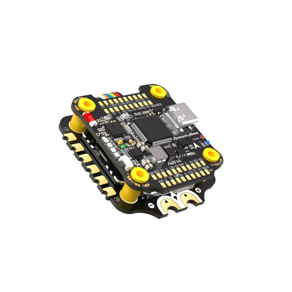
| Product Name |
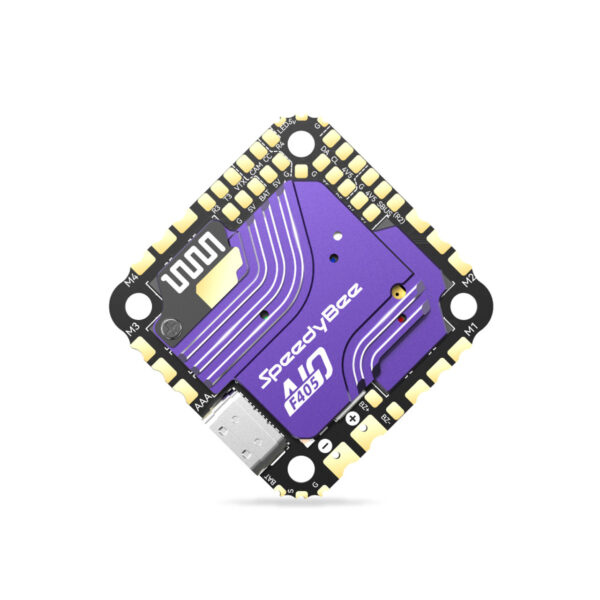
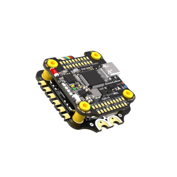
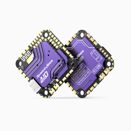
SpeedyBee F4S V4 30x30 Flight Controller |
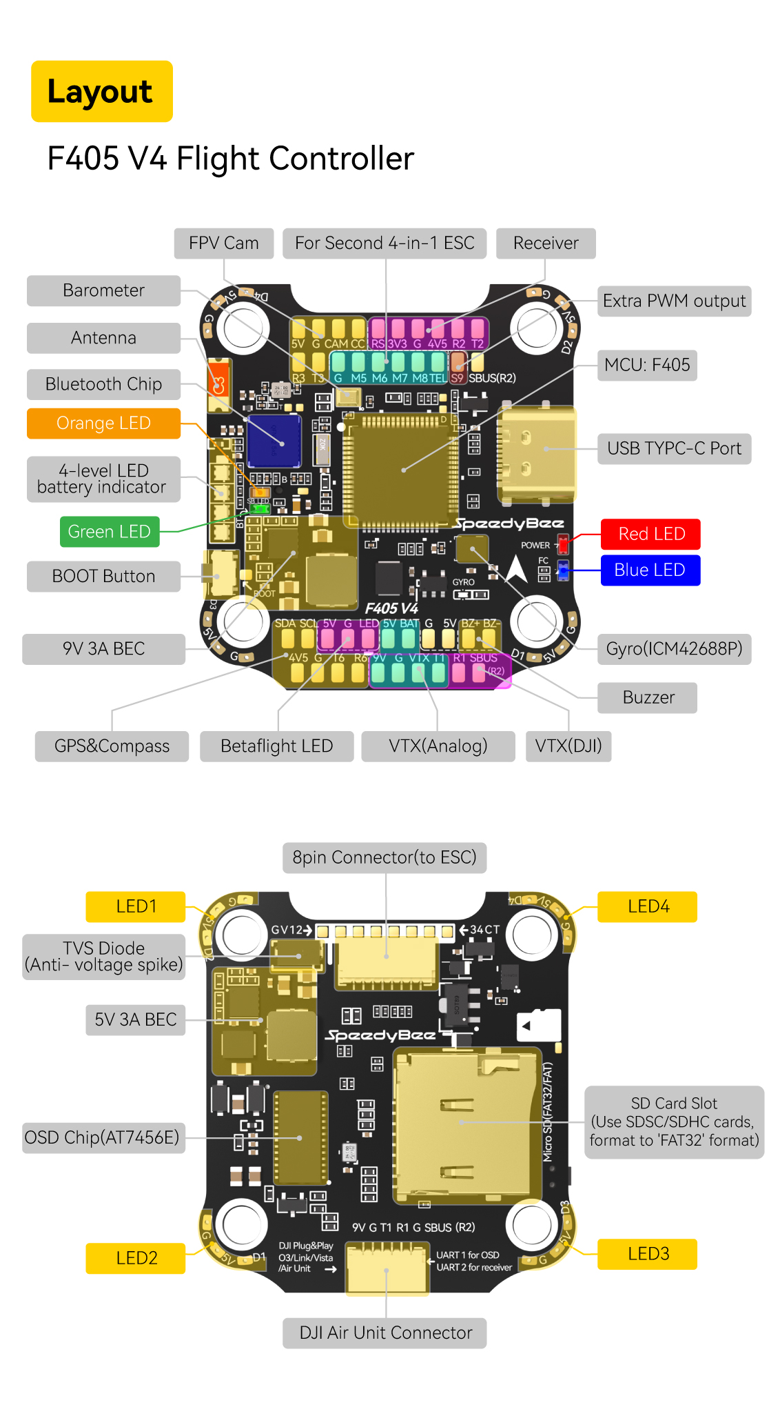
| MCU |
STM32F405 |
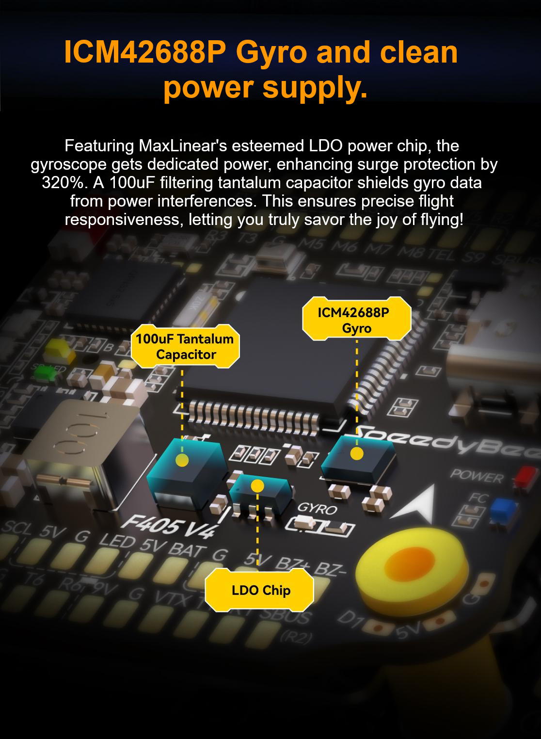
| IMU(Gyro) |
ICM42688P |
| USB Port Type |
Type-C |
| Barometer |
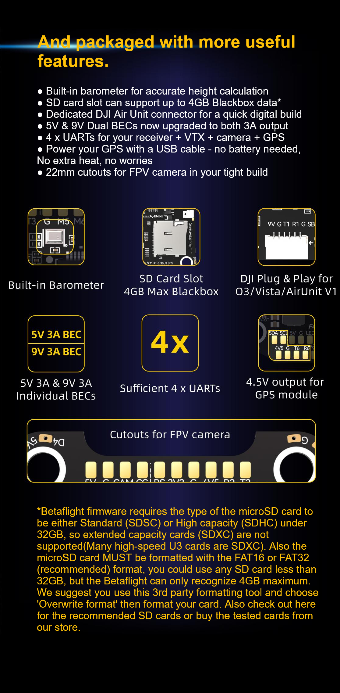
Built-in |
| GYRO Chip |
ICM42688 |
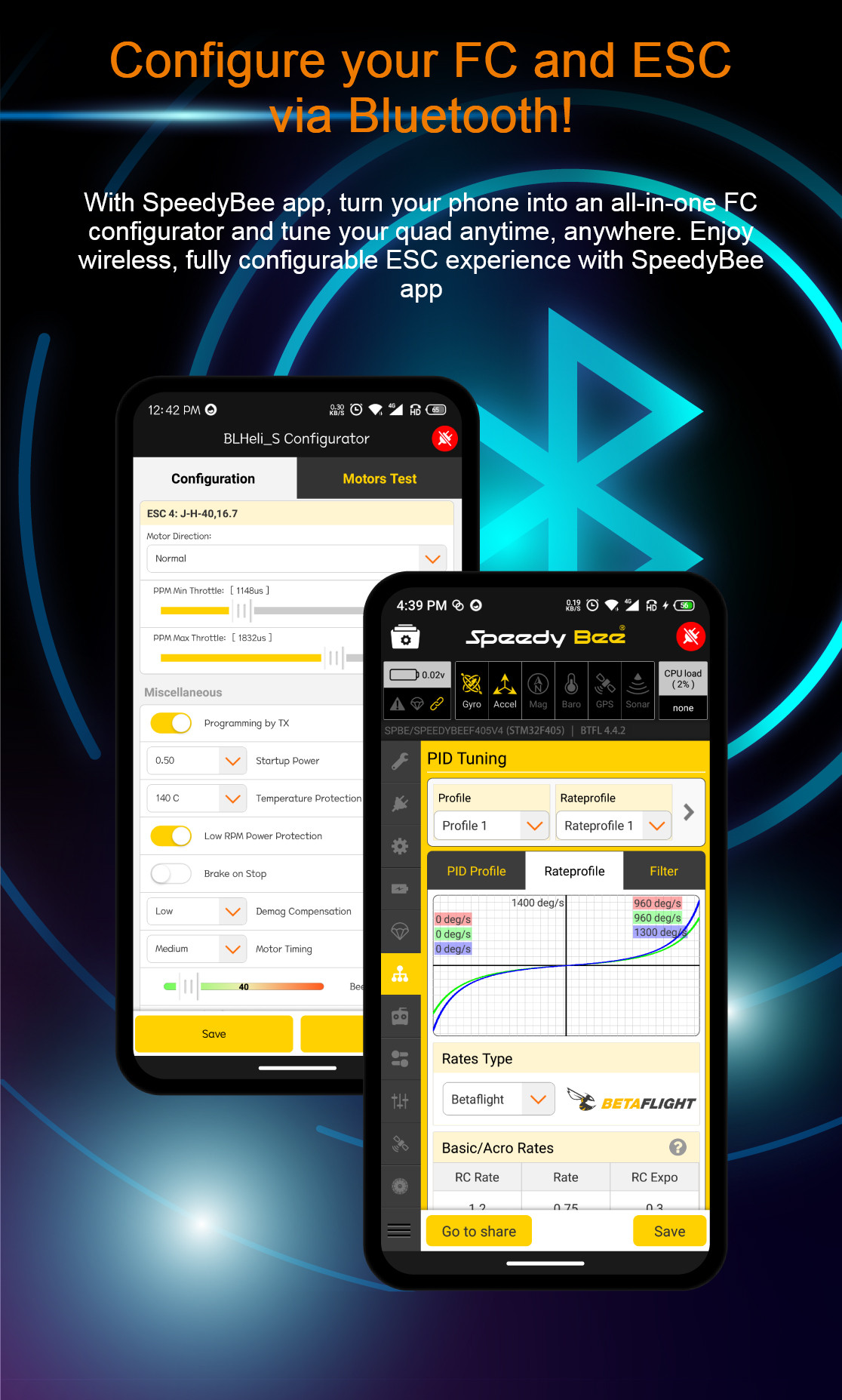
| BLE Bluetooth |
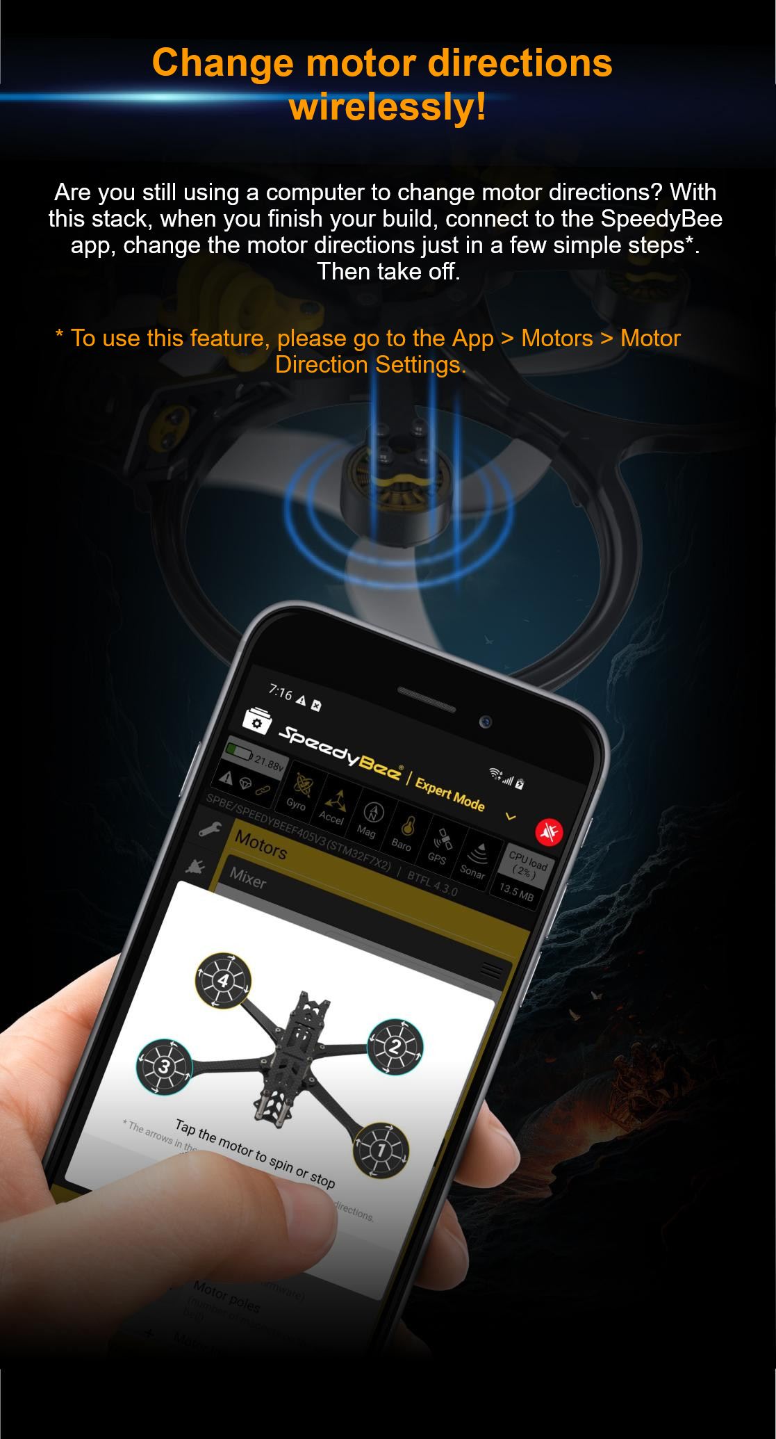
Supported. Used for Flight Controller configuration (MSP should be enabled with baud rate 115200 on UART4) |
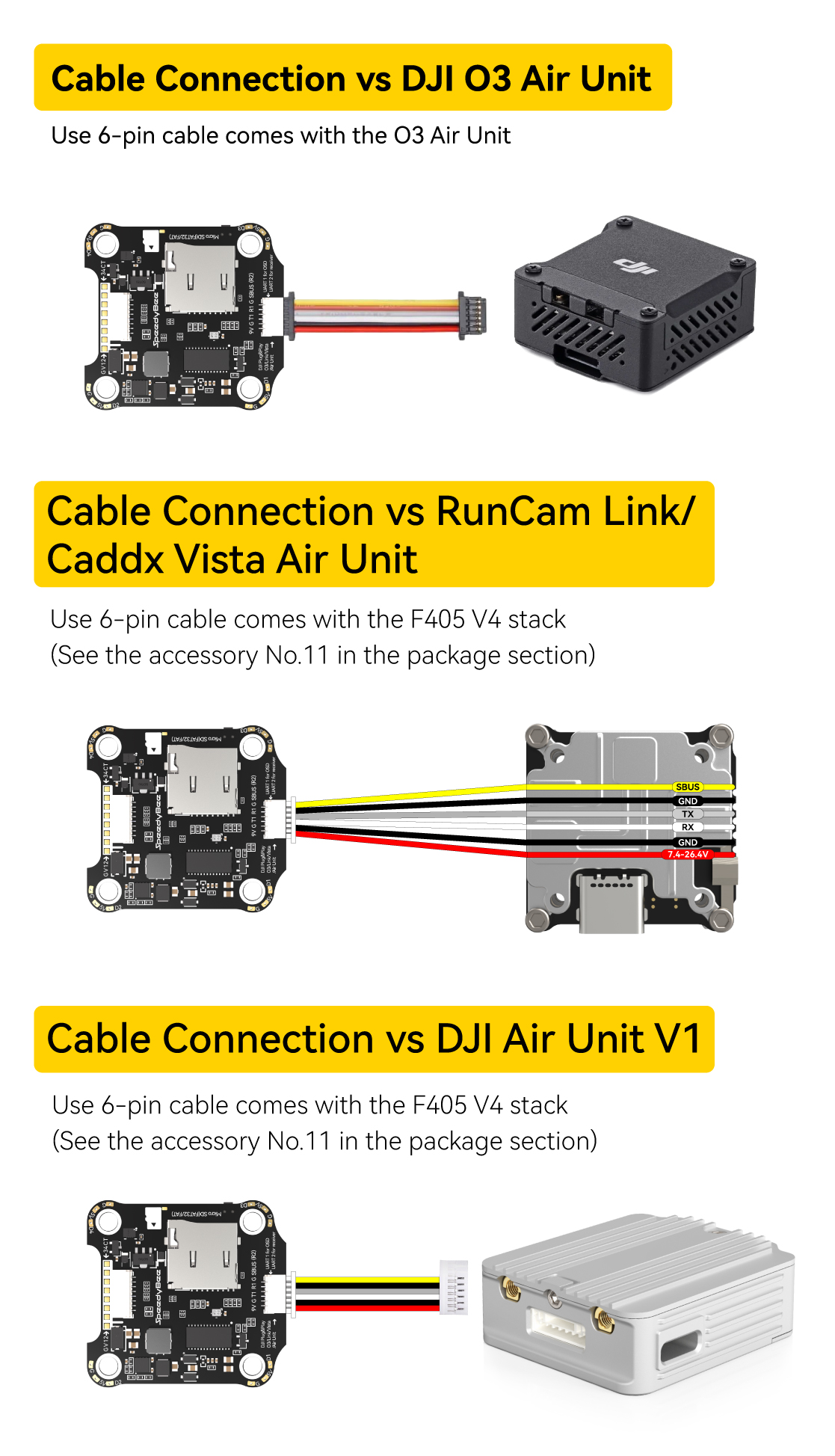
| WiFi Air Unit Connection Way |
Two ways supported: 8-pin connector or direct soldering |
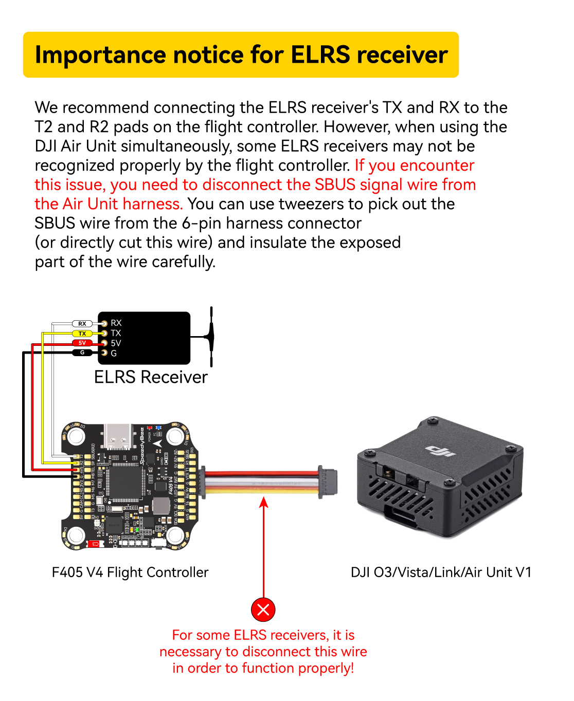
| 6-pin DJI Air Unit Plug |
Unit V1: wire is needed to be changed. Compatible compatible with DJI O3/RunCam Link/Caddx Vista Air Unit V1.
Unit V2: high-capacity (SDHC) under 32GB is recommended.
(SDXC or high-capacity SDHC under 32GB are not supported). |
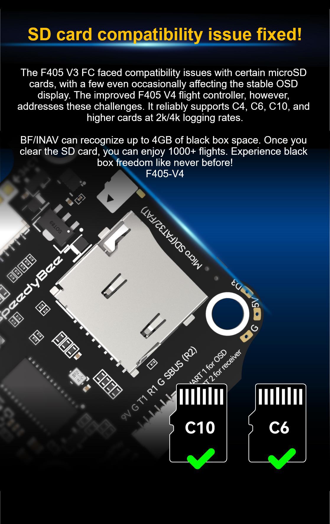
| Blackbox MicroSD Card |
MUST be formatted with the FAT16 or FAT32 format. It should use SD card less than 32GB. The Betaflight can only recognize 4GB maximum. We suggest you use this 3rd party formatting tool and choose "Overwrite format" then format your card. Also check option here for the recommended SD cards by format. |
| Current Sensor Input |
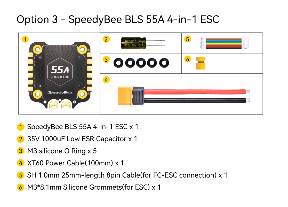
Supported. For SpeedyBee BLE 5S ESC, please set scale = 400 and offset = 0. |
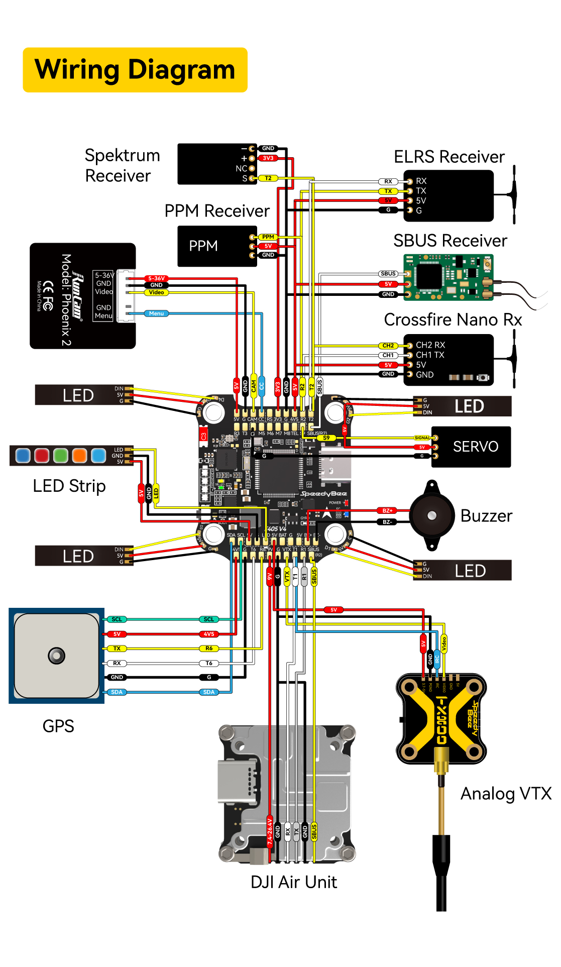
| Power Input |
3S - 6S (LiPo through G, B+ pins) pads from the 6-pin connector or 8 pads on the bottom side)
9 groups of 5V output, 4-6V pads and 8-24V (used for Buzzer) on front side, and 4x LED 5V pads. The total current load is 3A. |
| 5V Output |
Supported. Designed for 3.3V input receivers. Up to 800mA current load. |
| ESC Signal |
Through the USB port. Up to 1A current load. |
| UART |
6 sets(UART1, UART2, UART3, UART4)(Dedicated for Bluetooth connection). |
| ESC Telemetry |
UART5(UART5). |
| I2C |
Supported. SDA & SCL pads on front side. Used for magnetometer, sonar, etc. |
| Traditional Betaflight LED Pad |
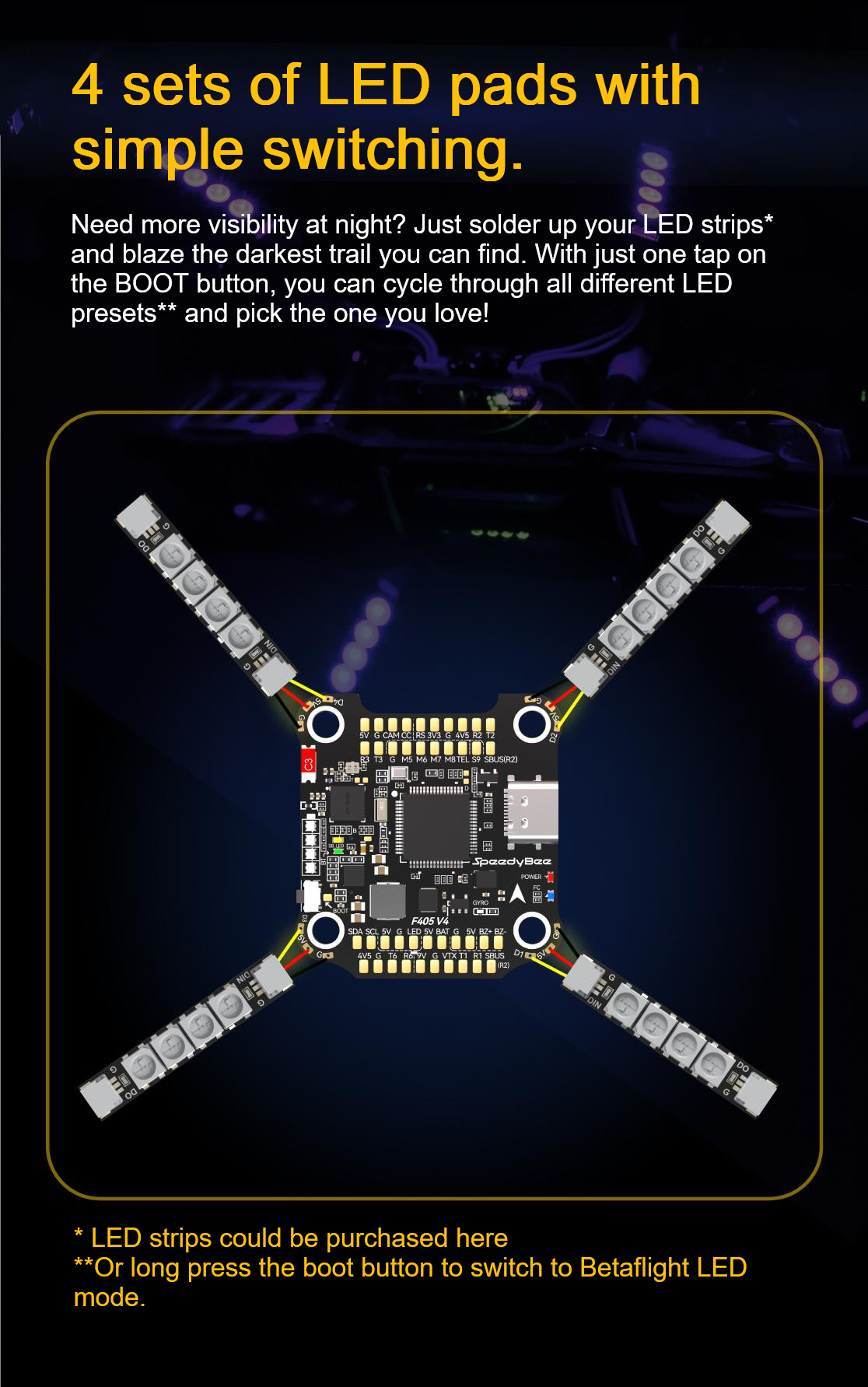
Supported. 5V and LED pads on bottom of the front side. Used for WS2812 LED strip. |
| Buzzer |
8-2 and B+ pad used for 5V Buzzer. |
| BOOT Button |
Press and hold BOOT button and power the FC at the same time will force the FC to enter DFU mode, this is for firmware flashing when the FC gets bricked.
When the FC is powered on and in standby mode, the BOOT button can be used to control the LED strips connected to LED1-LED4 connectors on the bottom side. By default, short press the BOOT button cycle the LED displaying mode. Long press the BOOT button (2 seconds) to turn off the LED strip completely. Under DFU mode, all the LED strips will be controlled by Betaflight firmware. |
| RSSI Input |
Supported. Named as RS on the front side. |
| Smart Port / F.Port Controller |
Not supported. |
| Firmware |
BetaFlight(default), INAV |
| Firmware Target Name |
SPEEDYBEEF4S |
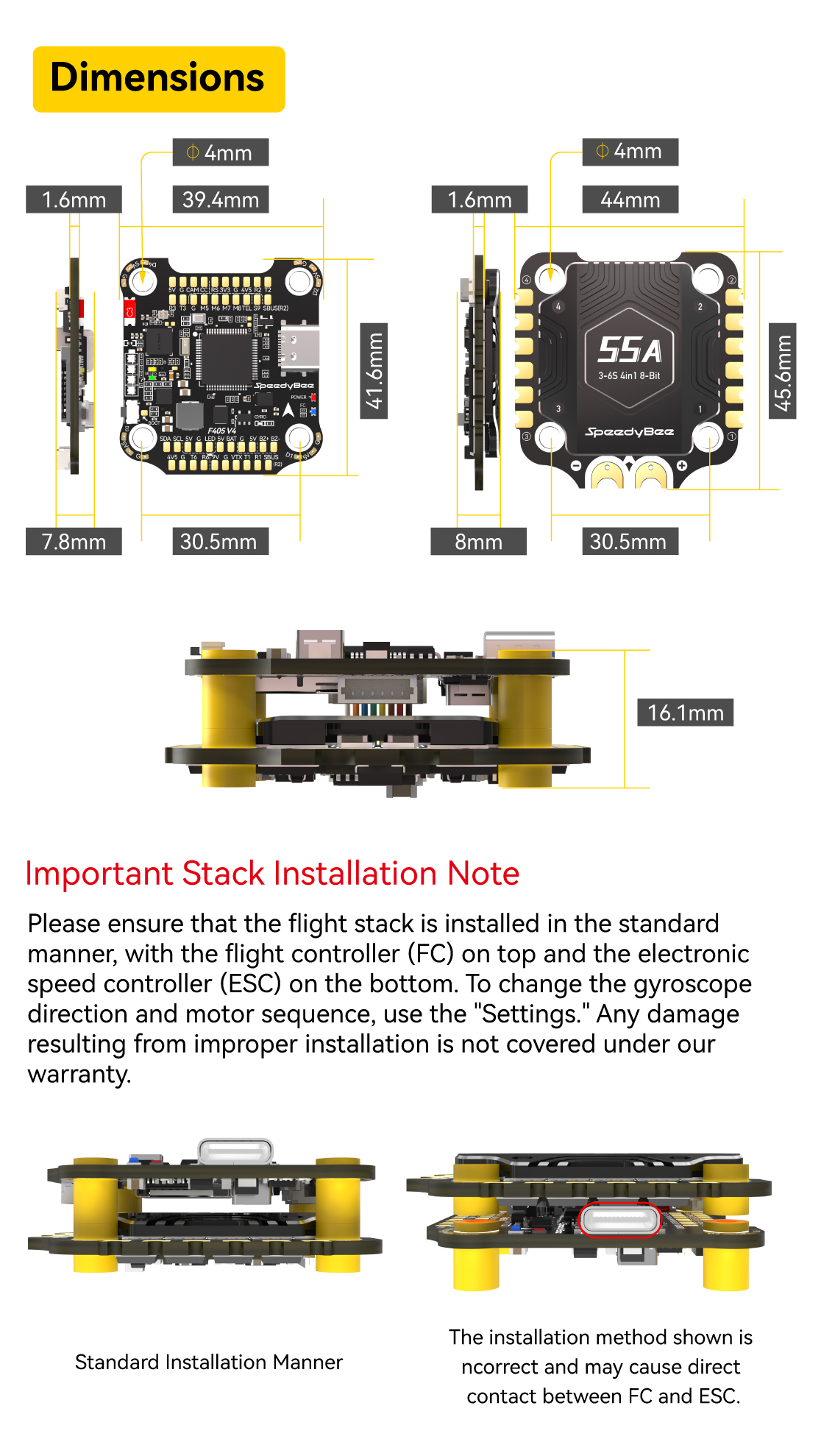
| Mounting |
30.5 x 30.5mm (4mm hole diameter) |
| Dimension |
41(L) x 39.4(W) x 7(H)mm |
| Weight |
10.5g |


Reviews
There are no reviews yet.